DESIGN FOR MANUFACTURING (DFM): TEUFEL MYND OPEN-DESIGN CASE STUDY

Recently, iterator.de revisited the MYND portable speaker system by Teufel, an open-design concept known for its elegant form and strong acoustic profile. Like many open hardware projects, the available files appeared to originate from a development snapshot—more of a design showcase than a production-ready solution. We undertook a full DFM and DFAM (Design for Manufacturing / Additive Manufacturing), analysis and redesign: simplifying assemblies, adjusting tolerances, introducing chamfers and roundings to distribute shrink stress, and modifying key geometries for better print-bed adhesion. These changes brought the design in line with both traditional production requirements and additive workflows—without compromising its original character.
As you read on, we’ll dive deeper into this transformation, breaking down specific design decisions and showing how DFM and DFAM principles shaped the final result. Whether you're designing open hardware or planning your next prototype, the lessons from MYND apply broadly—and might just save your next great idea from becoming a manufacturing headache.
A Quick Background on the Project:
We got a call from Computer Bild—they were working on a feature about the Teufel MYND speaker and wanted some parts printed. What caught their attention was the availability of open-source files for the entire assembly, including the PCB and power electronics. We took a look at the project files and instead had to offer them our perspective because the design didn’t fit our manufacturing rediness criteria. The question quickly became: what’s the state of the open design? So we dove in.

DFM & DFAM In Context:
In product development, a brilliant idea is only half the battle—the rest lies in making that idea manufacturable. Design for Manufacturing (DFM) is the discipline of refining a product so it can be produced efficiently, reliably, and at scale using real-world materials and processes. While creativity fuels the concept, DFM ensures it survives the transition from sketch to shelf without introducing unnecessary cost, complexity, or waste.
At its core, DFM is about aligning design intent with manufacturing capability. This involves selecting the right materials and processes early—be it injection molding, CNC machining, or additive manufacturing—reducing part counts, standardising features, and eliminating difficult-to-produce elements. It’s where engineering meets strategy, and where smart design choices can prevent expensive production mistakes later down the line.
But DFM isn’t just about cost-cutting or efficiency. It’s about designing with clarity and foresight, so that everyone involved—from the machine operator to the end user—gets a better experience. It empowers engineers to avoid rework, manufacturers to reduce scrap, and users to enjoy products that feel thoughtfully built. In an age of sustainability pressures and agile development cycles, DFM becomes a key enabler of speed and responsibility.
One area where this is especially critical is Design for Additive Manufacturing (DFAM). Unlike traditional processes, additive methods like FDM and SLS unlock new possibilities—complex internal geometries, organic forms, and on-demand production—but they also come with unique constraints. Warping, weak overhangs, poor bed adhesion, and anisotropic strength are just a few of the challenges that make it essential to rethink how parts are designed. Simply exporting a CAD file to a slicer isn’t enough. DFAM means tuning a design to the realities of the medium: layer orientation, surface finish, material behavior, and support strategy all play vital roles.
It’s also important to remember that not all additive manufacturing technologies are created equal. Each has its strengths and trade-offs—what works beautifully on an industrial SLS or MJF machine might fail completely on a consumer-grade FDM printer. And since most makers and hobbyists rely on accessible platforms like FDM or DLP, open-source designs must reflect this reality. The best open designs aren’t just clever—they’re considerate of the limitations and capabilities of the wider maker community. A masterpiece that only prints on a 200k€ machine isn’t much use on a 500€ one.
Where Did We Start?
We began by performing a 3D model analysis of the plastic components one by one, and right away, we spotted a few boundary errors—specifically in the grille and HMI (Human-Machine Interface) cover. This was surprising, to say the least, but could also be a simple import error. These types of issues essentially break the model’s integrity, turning what should be a solid 3D object into a hollow, non-manifold shell. For 3D printing, that’s a major problem: slicer software (which converts 3D models into machine instructions) can miss these, stall or fail entirely when it encounters such geometry. These errors can occur during the export, import and format conversion phase (we used the STEP files for this project), but given that these errors can be common in 3D file repositories world-wide, let’s take a closer look at this problem.

Notice how three sides of this rib are missing? Until those are bridged and stitched, the model remains a surface body rather than a true solid. This kind of geometry breaks manifold integrity, meaning most slicer or simulation software will interpret it as a hollow shell—not a functional 3D part.
As an industrial design studio working with CAD on a daily basis, iterator.de had no trouble professionally repairing these issues. However, for the average hobbyist or maker, errors like these can become a real Achilles' heel—especially without access to advanced tools or the experience required to perform manual model repairs.
While some slicer and CAD programs offer automated mesh repair tools—Netfabb, for instance, is available both as a standalone utility and integrated into platforms like Autodesk Fusion—the results can be inconsistent. In many cases, manual intervention still produces the most reliable outcome, particularly when preparing a model for real-world manufacturing or assembly.
The second boundary error we addressed involved the grille. Both the base of the circular recess and the surrounding perimeter wall were entirely missing and we had to guess it would be the same as the recesses next to it. To fix it, we first measured the depth of the adjacent geometry, then used surface extrusion to recreate the missing perimeter at a consistent height. Finally, we capped the bottom and stitched the surfaces together into a watertight solid, bringing the model up to a functional, manufacturable state—exactly as it should have been from the start.

See the five complete circular recesses surrounding the gold area? It might be a bit tricky to interpret at first, but here’s what’s happening: the gold color represents the back face of the surface—meaning we’re actually looking through the model. The faces that should define the recess are missing entirely, exposing the inner surface. This is exactly why the model was stuck in a surface-body state—it wasn’t watertight, and the geometry couldn’t be interpreted as a solid.
With all parts now solid, next we conducted a full DFAM analysis on the 3D assembly—focusing inintially on the two largest housing parts for the main speaker unit. Remember, given that this is an open design, it's reasonable to assume that most users will be hobbyists or semi-professionals. As a result, additive manufacturing—particularly desktop FDM or DLP—will likely be the method of choice. With that in mind, we applied a DFAM framework to guide our assessment and modifications.
The first and largest candidate for review was the main speaker housing. As the central structural component, it had the greatest impact on printability, assembly, and part performance. We looked at overhangs, wall thicknesses, stress concentration zones, and unsupported features—all with an eye toward improving print success rates and structural reliability on low-cost 3D printers.

Here’s a look at the housing laid on it’s back with some of its internal features visible.

Here’s a cross-section view of the housing. Most of the wall thicknesses measure around 3mm, which is generally sufficient for 3D printing. However, given our recommended print orientation for this part (which we’ll cover shortly), this thickness isn't ideal—especially in areas subject to dynamic loading, such as where buttons are pressed on the HMI. That said, it’s not a dealbreaker at this stage, but it’s definitely something to monitor as we move forward in the design validation process.
Our first overall impression of the housing was clear: it had been designed with injection moulding in mind—not 3D printing. The rear wall features a grid of ribs, likely intended to provide rigidity and help anchor internal components like electronics, while maintaining their relative positions. While these structures aren't inherently DFAM-prohibitive, but they do often complicate printability. Removing or adapting them for additive manufacturing—possibly by thickening walls and simplifying geometry—would require significant effort.
More critically, the housing lacked even the most basic DFM and DFAM fundamentals: very few chamfers and fillets were identified where geometry changed direction. In both injection moulding and 3D printing, sharp internal corners and abrupt transitions become high-risk fracture zones. As thermoplastics cool, they shrink slightly, introducing stress at these hard edges. Without proper rounding, parts are prone to warping, delamination, or even breakage—either during printing or under stress during assembly and use.
We approached the problem methodically, inspecting the housing from every angle and applying a full DFAM revision: filleting stress-prone edges, adjusting wall thicknesses, and modifying internal structures to reduce unsupported spans and improve bed adhesion. It took a considerable amount of effort—and not every edge or corner was easily adaptable—but we reached a point where 99% of the geometry met our DFAM-ready criteria.

Example of screw bosses without any roundings at their bases. Without them, they can tear or warp other design features as they cool during the manufacturing process.

Example with roundings added to these features. This spreads the tension evenly and gradually around the mechanical features as the material cools.
The next step in making the model DFAM-ready was selecting the optimal print orientation. Printing the housing upright simply wasn’t practical—there are too many internal features and extensive overhangs that would require a large amount of support material, leading to longer print times, wasted filament, and a rougher finish. Instead, the part is best printed lying on its back, which minimizes support needs and improves overall print quality. This decision comes with its own drawbacks, as the print direction will weaken the areas between the HMI button holes.
However, this introduced another issue: the back surface of the housing wasn’t flat, which meant poor print bed adhesion—a common cause of warping or failed prints, especially on FDM machines. To address this, we modified the geometry to create a clean, stable footprint for the printer bed. This small change significantly improves first-layer bonding and overall print success, making the design far more reliable for everyday makers.

Here’s a view of the rear side of the housing. Notice the blue surface—it’s recessed by a few millimeters, which presents a clear issue for DFAM.
In its original state, the entire housing would need to be printed on a large support structure. Given the part’s size and geometry, this would almost certainly lead to warping, tearing, and poor surface finish, especially on common FDM printers. Compounding the problem, the surrounding faces are sloped, making it difficult to achieve stable bed adhesion. To resolve this, we created a modified back surface design that provides broad, flat contact with the print bed while preserving the original geometry as much as possible. While some shallow supports are still required, they’re minimal and won’t negatively impact print quality or ease of post-processing.
An alternative approach could involve flattening the entire back surface and adding embossed text or a subtle pattern to improve visual appeal—especially for makers who care about the final look as much as the function. This is the route we took, but as with all open-source designs, you're encouraged to adapt it to suit your tools, preferences, and priorities.

Our solution: we extruded the back surface using a clean, functional design that ensures reliable print bed adhesion, increases wall thickness, and provides a robust platform for mounting the internal electronics.
Next, we turned our attention to the grille. From the start, it was clear this part should be printed flat. However, printing it face down posed a high risk of failure due to the dotted texture on the front surface, which could interfere with first-layer adhesion and result in a poor finish. Flipping it over, we found an uneven back surface and several thin pin features that were unlikely to survive printing or repeated use.
One option was to reinforce the pins and then adjust the tolerances of their mating holes accordingly. But this wouldn’t address the underlying adhesion issue. Instead, we chose a more reliable approach: we removed the pins entirely and added several additional screw holes. This not only improved mechanical stability but also freed up more flat surface area for better bed adhesion—critical for reliable printing, even if the central portion still requires support.
We also identified reinforcing ribs along the inner perimeter of the grille frame. While these features are common in injection molding to add stiffness, they’re unnecessary in DFAM. 3D-printed parts already benefit from inherent layered structural rigidity, making such features redundant. We removed them to simplify the geometry and improve overall printability—without compromising strength or function.

Original grille with all its mechanical features.

DFAM ready grille with the four central pins replaced with screw holes and obsolete mechanical features removed.
At this stage, we had reworked two of the largest and most exposed components of the design to be fully DFAM-ready. From here, we had two options: continue diving deeper into the remaining parts, or hit pause and validate our adjustments with a test print. This is the beauty of 3D printing—you can iteratively test and refine your designs at any point in the process, making it an incredibly powerful tool for developing plastic parts.
Since this was a preliminary validation step, we chose to print the components at 50% scale to quickly assess overall geometry, fit, and structural behavior. Here’s how they turned out.

Here we have the DFAM-ready housing loaded into the slicer software. The green areas represent the support structures. As you can see, there are a few supports inside the housing, but they’re minimal and easy to remove. The majority of support material is concentrated on the exterior—some of it positioned in more complex areas—but overall, it remains manageable and well within the capabilities of most desktop FDM printers.

Here’s a view from underneath. The purple areas indicate solid infill, which is exactly what we want. This dense infill provides strong adhesion to the print bed and creates a rigid foundation for the rest of the housing to build upon—crucial for maintaining dimensional accuracy during printing.

Top view of the 3D printed grille and housing. All features printed successfully.

A bottom view of the grille and housing. Bed adhesion was good and the quality of visible surfaces was preserved.
Next, we moved on to the baffle—arguably the most complex component in the assembly. We followed the same DFAM workflow: geometry analysis, identifying the optimal print orientation, adding fillets and roundings, removing unnecessary features, and adapting others to align with changes made to adjacent parts.
Since the baffle is an internal component, hidden beneath the grille, it’s perfectly acceptable for the front-facing surface to be the print bed side, even if it requires a significant amount of support. What really matters is the rear surface, which needs to be as clean and precise as possible to ensure proper speaker mounting. We saw in the assembly tree that a seal has full contact with the rear side of the baffle, where any surface defects here could compromise ingress protection (IP) by creating gaps where water or dust could penetrate—so achieving a solid, reliable sealing surface was a top priority.

Front view of the baffle plate. It’s complex and will need several changes.

Rear view of the baffle plate. This is the side where the speakers are mounted to, and given its complex geometry, will be the top side of the 3D print.
In the first step, we converted the original pin sockets—which had been removed from the grille—into matching screw bosses on the baffle. The original design also included clip features intended to help secure a rubber seal beneath the baffle plate during assembly. While useful for mass production, these clips aren't necessary for low-volume or DIY manufacturing.
Given that print bed adhesion is already a challenge for this part, we opted to remove the clip features entirely, creating four clean contact zones around the frame of the plate. This improves first-layer adhesion and helps ensure a stable, successful print—without sacrificing the part’s ability to seal or perform its function.

Before: seal clipping areas in blue. This is insufficient suface area for reliable print bed adhesion.

After: areas in blue will have direct contact with the print bed. Everything else inside will be printed on supports.

The baffle face down in the slicing software. This is what we were expecting.
We were also curious to see how the changes to the baffle lined up with the rest of the assembly - especially the grille - so we printed this too at 50% scale. With this step done, we could move on to the smaller rubber parts - the main seal, feet and HMI cover.
The main seal didn’t require many adjustments. Some strengthening ribs on the rear side were shaved off to give us a clean surface for print bed adhesion, then we went through and added fillets to the areas where geometry direction changes were present.

Original main seal: nice, quick tidy up for DFAM.
The rubber feet and inserts were relatively straightforward to adjust and validate. The feet were essentially ready for production as-is, though it’s worth noting that the original design assumes they’ll be glued into place—a method that’s fine for low-volume assembly but could be reconsidered for users who prefer mechanical fastening or easy replacement.
As for the inserts, all four were identical, so we only needed to rework a single model before replicating the adjustments across the rest. However, the original design orientation assumed a vertical print, which presented problems. Printing them upright offered minimal surface area for bed adhesion and introduced unnecessary risk of tipping or warping, especially on lower-end FDM machines.
To address this, we shaved a small flat along the spine between the arrows of each insert to create a stable horizontal contact surface for printing. This allowed us to lay the part flat, improving both adhesion and dimensional consistency, while preserving all functional geometry. A simple adjustment, but one that significantly improves print reliability and user-friendliness.
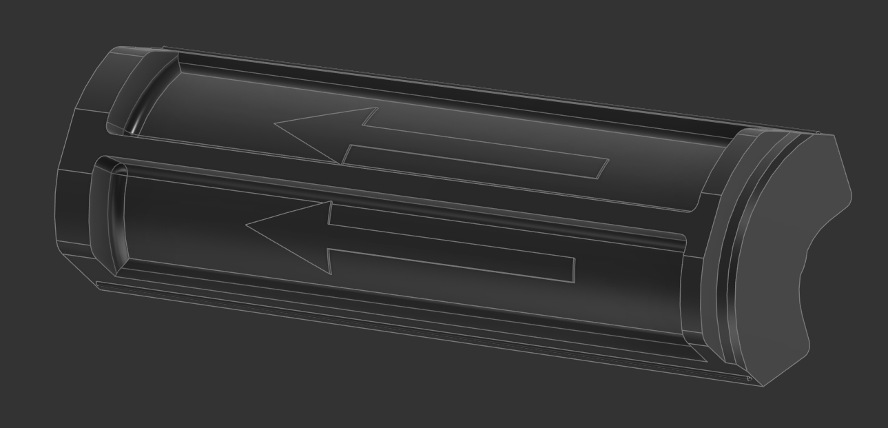
Rubber insert post DFAM: we trimmed a small section along the main spine to give a clean contact point for print bed adhesion, and filleted remaining geometry.
The HMI rubber pad required only minimal modifications. The original design used standard chamfers around the button recesses, which are generally fine in rigid materials—but less ideal for flexible components under repeated dynamic loading. Sharp angles can become stress concentrators in soft materials, increasing the risk of tearing over time. To improve durability and lifespan, we replaced these chamfers with smooth roundings, allowing for a more even stress distribution during use.
As for print orientation, this part is straightforward. To preserve the integrity of the button icons and achieve a clean, functional surface finish, the pad should be printed face-up, with the icon side exposed. This orientation minimizes post-processing and ensures that tactile feedback and legibility are maintained—both critical for a part that’s touched frequently during use.

HMI pad: easy peasy and DFAM ready.
Lastly, we turned our attention to the remaining plastic components: the PR-frames, HMI cover, and port housing. Of these, the PR-frames required the most attention. Originally designed for high-volume production, they featured a front-facing lip used to align the speakers with their mounting holes during assembly. While this is useful in injection molding workflows where jigs and fixtures are standard, it’s unnecessary—and even problematic—for additive manufacturing, where such fine features often introduce overhangs and complicate print orientation. We removed the lip entirely to simplify the geometry and make the parts more printable.
Next, we added fillets where possible to reduce stress concentrations and improve overall part strength. Some areas were too tight or irregular to accept clean fillets without more significant redesign. Given the time constraints of this project, we opted to leave those areas as-is, allowing the slicer software to interpolate the geometry and generate appropriate toolpaths. While not ideal in a production-grade model, this was a practical compromise that still yields functional, printable parts for low-volume or prototype builds.

PR frames (left and right): one with the lip removed.
The HMI cover required a similar round of adjustments, though overall it was quicker to bring in line with DFAM standards. Most of the critical mechanical features—mounting points, alignment structures, and contact surfaces—are located on the underside of the part. Because of this, the most logical print orientation is face down, ensuring that these features are well-supported during printing and maintain dimensional accuracy.
We applied the usual DFAM refinements, including filleting sharp edges, simplifying unsupported overhangs, and verifying wall thicknesses to avoid weak points during assembly or use. The chosen orientation strikes a good balance between surface quality and functional accuracy, making the part both quick to post-process and mechanically reliable straight off the print bed.

The HMI cover: DFAM ready and ready to print.

The port housing: touched up and prints really nicely.
Last but not least, we tackled the port housing—a small but important component. Fortunately, this part required only minimal adjustments and was quick to bring up to DFAM standards. With that, the full sweep of modifications for the MYND speaker system was complete.
This is the kind of effort that transforms an interesting open design into something reliable, repeatable, and truly community-ready. By resolving structural issues, refining geometries, and adapting the design for accessible manufacturing methods, we’ve helped make MYND more approachable for makers at all levels.
You can find the link to our DFAM-optimized remix of MYND on Thingiverse below.
Original files: https://teufel.de/mynd-107002004#pdp-support
iterator.de MYND DFAM Remix: https://www.thingiverse.com/iterator_design_berlin/designs https://www.thingiverse.com/thing:7081243